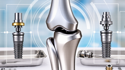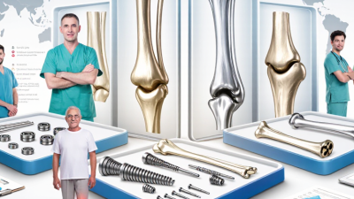
Precision implant fit design begins with a practical question: how accurately can an implant restoration match the patient’s anatomy, function, and clinical conditions? A successful fit is more than a clean digital model. It depends on bone volume, implant position, soft-tissue contours, occlusal forces, and the restoration material. Each factor can influence comfort, stability, hygiene, and long-term maintenance. Experienced clinicians combine CBCT imaging, intraoral scanning, diagnostic photographs, and careful clinical examination. Digital planning can reveal risks before surgery, such as limited bone width or an unfavorable emergence profile. However, technology does not replace clinical judgment.
Reliable design requires controlled steps and honest verification. The dental team should check scan quality, confirm implant connections, and review the proposed occlusion before manufacturing. Small errors can appear when scan bodies are poorly seated, surfaces are contaminated, or multiple scans are stitched together. A few microns on screen may become a noticeable contact during insertion. Try-in procedures, radiographic confirmation, and passive-fit assessment provide valuable evidence. Still, no workflow removes every uncertainty. Patient movement, healing changes, and soft-tissue behavior can challenge even a carefully planned case. That limitation deserves attention. Precision implant fit design should therefore be treated as an iterative process, not a single digital command. By combining validated systems, documented measurements, laboratory expertise, and clinician experience, teams can create restorations that fit the patient rather than merely fitting the software.
How to Achieve Precision Implant Fit Design?
Defining Precision Implant Fit and Its Clinical Importance
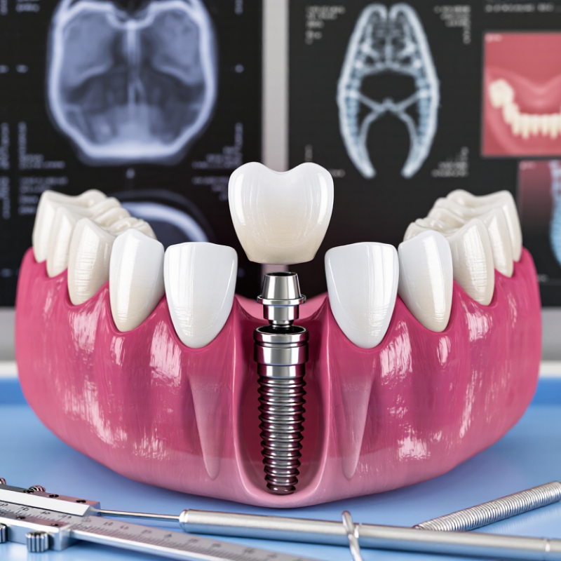
Precision implant fit means stable, intimate contact between implant components, abutments, and the final restoration. It is not simply a beautiful digital model. A passive fit should avoid visible gaps, rocking, and excessive tightening. The 2023 ITI Consensus Report notes that no universal misfit threshold has been clinically validated. That uncertainty matters. A gap may look harmless on screen, yet behave differently under chewing forces. A systematic review of long-term implant restorations reported survival near 90%, while technical complications remained frequent. Fit is therefore a risk-control decision, not a cosmetic detail.
Poor fit can concentrate stress around screws, interfaces, or supporting bone. Patients may notice movement, food trapping, or repeated screw loosening. Clinicians may see polished metal, but not the hidden strain. Digital scanning improves records, although it cannot correct tissue movement, unstable scan bodies, or laboratory inaccuracy. The design must also respect available space, angulation, occlusion, and cleaning access. Perfect fit is an ideal, not a guaranteed event. That deserves honest discussion.
Tips: Verify scan-body seating clinically. Inspect margins under magnification. Use radiographs when interfaces are unclear. Avoid forcing components together with excessive torque. Record the torque value and reassess occlusion after loading. Independent quality checks help, but they do not replace clinical judgment.
Precision implant fit is evaluated through marginal adaptation, internal adaptation, and controlled cement space. The reference values below are commonly cited design targets in implant prosthodontic literature; they should not be treated as universal pass-or-fail limits.
Lower gap values generally indicate closer adaptation. Clinical outcomes also depend on impression or scanning accuracy, framework manufacturing, seating, occlusal control, and verification of the final restoration.
A precise implant fit begins with a careful reading of the patient’s anatomy. Clinical examination should assess bone volume, soft-tissue thickness, bite forces, and nearby nerves. Three-dimensional imaging can reveal narrow ridges, sinus boundaries, and hidden concavities. Digital measurements help, but they do not replace clinical judgment. The patient’s medical history also matters. Healing capacity, oral hygiene, and previous procedures may change the design.
Implant parameters should match the available anatomy and the expected functional load. Diameter and length must provide stability without approaching vital structures. Angulation should support a natural emergence profile and a cleanable restoration. The connection and restorative space require equal attention. A technically attractive plan can still fail if the patient cannot maintain it. Peer-reviewed evidence and established clinical protocols should guide decisions, while the treating clinician remains responsible for individual assessment.
Tips: Compare the scan with direct clinical findings. Check bone thickness in several planes. Allow space for soft tissue. Confirm the planned position with a restorative design. Discuss alternatives, limitations, and possible revisions with the patient. Small errors matter. I have found that the first digital plan is rarely perfect. Rechecking it against the patient’s actual bite often exposes assumptions that seemed reasonable on screen. Flexible planning is not weakness; it is safer clinical practice.
Precision implant fit begins with geometry that respects both bone and soft tissue. A rigid shape may look accurate in CAD, yet fail around curved anatomy. Use patient-specific imaging to map cortical thickness, internal contours, and local density. Small variations matter. A 0.2-millimeter mismatch can create unwanted pressure or a visible tissue transition.
The implant body should distribute loads gradually, rather than concentrate them near one edge. Rounded transitions reduce stress around the interface. Surface texture and thread depth should match the intended bone response, but geometry must not be designed from imaging alone. Surgical access, manufacturing tolerance, and placement error also need review. In design meetings, I have found that the “perfect” model often needs practical compromise. That is not failure. It is responsible engineering.
Tips: Keep the emergence profile smooth and anatomically restrained. Check clearance in three dimensions, including rotational placement. Compare the design with multiple imaging views. Ask whether soft tissue has enough room to heal without compression. A useful review also includes worst-case tolerances, not only the ideal fit. When evidence is limited, document the assumption and request clinical validation before production.
How to Achieve Precision Implant Fit Design?
Using Digital Planning and Manufacturing to Control Fit Accuracy
Precision implant fit begins with reliable digital information. In clinical workflows, intraoral scans and CBCT data must be aligned carefully. Small registration errors can shift the planned position. That affects emergence, occlusion, and soft-tissue support.
Digital planning helps teams examine bone volume, implant angulation, and restorative space before manufacturing. Experienced designers use virtual measurements, not visual guesses alone. They also review scan quality, missing surfaces, and patient movement artifacts. Details matter. A perfect-looking model may still contain inaccurate data.
Manufacturing control is equally important. Milling or printing parameters should match the selected material and design tolerance. Machine calibration, tool wear, resin shrinkage, and post-processing can change the final fit. Each manufactured component needs inspection against the approved digital file. A physical gauge or high-resolution measurement system can reveal gaps that software misses.
A digital file is not truth. It is a controlled plan that requires verification. In practice, communication between the clinician, designer, and technician prevents many avoidable adjustments. Yet no workflow is flawless. Seating resistance may expose an overlooked undercut or an inaccurate scan boundary. That feedback should improve the next case, rather than be dismissed as a minor inconvenience. Consistent records, documented tolerances, and repeatable checks make precision more dependable.
| Workflow Dimension | Practical Control Range or Target | Measurement Method | Primary Accuracy Risk | Recommended Quality-Control Action | Evidence Basis |
|---|---|---|---|---|---|
| CBCT voxel size | 0.08–0.30 mm | Review DICOM acquisition parameters before planning. | Small anatomical structures may be blurred when the voxel size is too large. | Select the smallest clinically justified voxel size while controlling radiation exposure and image noise. | Commonly reported dental CBCT acquisition range; actual settings depend on the clinical indication. |
| Intraoral-scan trueness for full-arch records | Approximately 20–100 µm | Compare the scan with a calibrated reference using 3D deviation analysis. | Scanning strategy, saliva, soft-tissue movement, stitching drift, and long-span geometry can reduce accuracy. | Use a controlled scan path, stable reference areas, and a repeat scan when stitching deviation is visible. | Typical range reported across peer-reviewed digital-impression studies; results vary by scanner, operator, and scan length. |
| Scan-body seating verification | No visible gap or rocking | Visual inspection, radiographic verification where indicated, and digital comparison with the planned library geometry. | Incomplete seating, debris, incorrect library selection, or screw instability can create a systematic positional error. | Clean the connection, verify complete seating, confirm the correct scan-body geometry, and rescan if uncertainty remains. | Established clinical verification principle; no single universal numerical tolerance applies to every implant system. |
| Implant-position deviation at the entry point | Commonly reported mean: about 0.5–1.0 mm | Superimpose postoperative CBCT data on the virtual plan and calculate 3D deviation. | Guide movement, tissue support, drilling clearance, and registration errors may shift the implant position. | Use rigid guide support, inspect seating before drilling, and maintain adequate safety distance from critical anatomy. | Typical range reported in guided-surgery accuracy reviews; individual cases can exceed this range. |
| Implant-position deviation at the apex | Commonly reported mean: about 0.7–1.5 mm | Measure the linear distance between planned and postoperative implant apices. | Small angular errors become larger at the apical end as implant length increases. | Use a deeper safety margin than the measured manufacturing tolerance when planning near nerves, sinuses, or adjacent roots. | Typical range reported in guided implant-placement literature; accuracy depends on the complete workflow. |
| Angular deviation | Commonly reported mean: about 2–5° | Calculate the angle between the planned and placed implant axes. | Drill deflection, guide sleeve clearance, incomplete guide seating, and operator handling can increase angular error. | Use a rigid, well-supported guide and verify the drilling components for wear, damage, and correct fit. | Typical range reported in systematic reviews of guided implant surgery. |
| CAD implant-interface geometry | Use validated library geometry; do not modify the connection | Check library version, implant platform, component type, and rotational orientation before manufacturing. | Incorrect library selection or unauthorized geometry changes can cause seating errors even when the part is dimensionally accurate. | Lock approved libraries, document the selected component, and perform a premanufacturing design review. | Digital-design control principle; implant-interface dimensions are system-specific and should follow the applicable technical documentation. |
| Manufacturing dimensional deviation | Typical precision-machining capability: ±0.02–0.05 mm | Inspect critical dimensions with calibrated gauges, a coordinate-measuring machine, or validated 3D scanning. | Tool wear, thermal expansion, machine calibration, material shrinkage, and post-processing can alter final dimensions. | Define critical-to-fit dimensions, calibrate equipment, record lot-level measurements, and use statistical process control. | Common precision-machining capability range; actual tolerance must be confirmed for the selected material and process. |
| Framework or abutment seating | Complete seating without rocking or visible misfit | Verify on the working model and, when clinically appropriate, use the one-screw test and radiographic confirmation. | Model inaccuracies, distortion, unsupported components, and accumulation of tolerances may produce passive-fit problems. | Use a verification index or sectional test when the span is long, the implant count is high, or the fit is uncertain. | Widely accepted prosthodontic verification practice; a universal numerical passive-fit threshold has not been established. |
| Final fit acceptance record | 100% documented inspection of critical interfaces | Record design version, scan data, manufacturing batch, inspection results, and clinician acceptance. | Untraceable revisions make it difficult to identify whether an error originated during imaging, planning, design, or production. | Use revision control, operator sign-off, calibrated inspection tools, and a nonconformance procedure. | Quality-management best practice based on traceability and process validation principles. |
| Interpretation note: The numerical values above are practical reference ranges reported in dental imaging, digital-impression, guided-surgery, and precision-manufacturing literature. They are not universal acceptance limits. Clinical safety margins, component-specific tolerances, material behavior, equipment validation, and applicable regulatory requirements must be confirmed for each case. | |||||
Precision implant fit is not confirmed by a digital file alone. A reliable design must survive testing, clinical placement, and careful follow-up. Before surgery, clinicians should compare the planned implant position with bone volume, soft-tissue contours, and the final restoration. A printed guide or provisional component can reveal pressure points, limited access, or an incorrect emergence profile.
Testing should include a controlled try-in, visual inspection, and radiographic verification when appropriate. The clinician checks whether the component seats completely without rocking. Occlusion also matters. A high contact can place unnecessary stress on the implant and surrounding bone. Small details matter here, such as a clean connection, stable seating, and enough space for hygiene tools.
Placement is not the end of the process. After insertion, the team should record torque values, tissue response, bite contacts, and patient comfort. Follow-up visits help identify mobility, inflammation, loosened components, or cleaning difficulties before they become serious concerns. Timing should follow the patient’s healing condition and the clinician’s judgment.
A perfect first pass is uncommon. That matters. One overlooked contact may only appear when the patient chews normally. Clinicians should remain willing to adjust the design, review the records, and question their assumptions. Clear documentation supports consistent decisions and gives future providers reliable evidence for maintenance.
We are committed to deliver solutions and transforming the way joint replacement procedures are performed.
Looking for the
Register as